Heat is one of the most overlooked risks in LED display operation. Excessive temperature can reduce brightness, distort colors, shorten component life, and trigger unexpected shutdowns. Outdoor billboards, stadium screens, and indoor video walls face different thermal conditions. Therefore, one universal solution rarely works.
This guide explains How to solve heat dissipation problems in LED displays through practical, engineering-based methods. It examines cabinet ventilation, aluminum structures, cooling fans, heat sinks, power supply placement, and environmental monitoring. It also considers pixel density, display brightness, installation direction, and protective ratings. These details matter because a tightly sealed cabinet may protect electronics from rain but trap hot air inside.
Field experience shows that small design choices create noticeable temperature differences. For example, clear airflow paths can prevent warm air from collecting behind modules. Thermal cameras can reveal hot spots that normal inspections miss. Temperature sensors provide useful warnings before failures become visible. Measure it properly.
However, cooling equipment alone does not guarantee reliable performance. Fans require cleaning, filters become blocked, and poorly selected components may add noise without removing enough heat. Some installations still surprise experienced technicians. Regular inspection, manufacturer specifications, and recorded temperature data support safer decisions. The ten approaches in this article combine proven practices with practical limitations. They are intended to help engineers, integrators, and display owners build a realistic maintenance plan, while recognizing that climate, cabinet design, and operating schedules can change the final result.
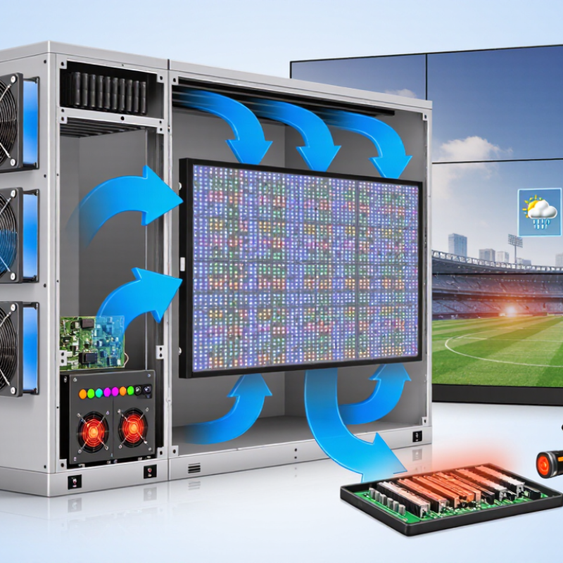
Understanding heat sources is essential before choosing a cooling method. LED chips convert only part of electrical power into visible light. The remaining energy becomes heat inside each pixel package. Driver boards, power supplies, cables, and connectors also create localized heating through electrical resistance.
Outdoor displays face additional heat from direct sunlight. A dark cabinet can absorb strong solar energy by midday. Restricted airflow makes this worse, especially when dust covers vents or filters. Poor contact between LED modules and metal mounting surfaces can create hidden hot spots. These areas may appear normal while accelerating component aging.
Measure before modifying the cabinet. Infrared cameras can reveal uneven temperatures, but reflective surfaces may produce inaccurate readings. Use a contact probe when readings seem doubtful. Check the display under full brightness, not only during a cool morning test. In practice, better heat paths often start with clean contact surfaces, firm module mounting, and suitable thermal materials. Natural airflow may work for a small installation, while larger systems need controlled fans or ventilation. Lowering peak current can reduce heat, although it may affect brightness and image uniformity. That trade-off deserves testing.
Small details matter. Leave clear air channels around power components. Separate heat sources where possible. Monitor internal temperature during seasonal changes. I have seen a clean cabinet outperform a more expensive design simply because airflow remained unobstructed. Still, no single solution fits every enclosure. Ambient temperature, pixel density, brightness settings, and installation position must be checked together.
LED chips convert only part of electrical power into visible light. The remaining energy becomes heat inside pixel packages. Driver boards, power supplies, cables, and connectors add localized heating. Small areas can become surprisingly hot.
Direct sunlight warms the cabinet, especially when its surface is dark. Midday rooftop exposure can create intense internal heat. Blocked vents make the problem worse. Dust can cover airflow paths. Shade helps, but it is not always practical.
Measure temperatures under full brightness and normal operating load. Check power supplies, receiving electronics, module backs, and cabinet corners. Infrared cameras can reveal uneven temperatures. Reflective surfaces may mislead them. Use a contact probe when readings seem doubtful.
Aluminum frames offer good conductivity, low weight, and corrosion resistance. Copper spreads heat faster but adds cost and weight. Graphite sheets can spread heat sideways in narrow spaces. The best material depends on enclosure size and mounting design. More expensive is not automatically better.
Tiny air gaps can act like insulation between modules and metal surfaces. Thermal pads or compliant fillers close uneven contact areas. Choose them by thermal resistance, compression range, insulation, and stability. A thicker pad may perform worse. Too much pressure can damage solder joints.
Natural airflow may work for a small, lightly loaded installation. Keep clear channels around power components. Separate major heat sources when possible. Larger displays usually need controlled fans or ventilation. Air must have somewhere to go.
Sensors should sit near the hottest module, not only near the cabinet entrance. A controller can increase fan speed gradually during heat peaks. It can also reduce brightness or send maintenance alerts. Fixed fan settings may waste energy in cool weather. They may react too slowly under direct sunlight.
Lowering peak current usually reduces heat generation. It may also reduce brightness or affect image uniformity. Test both temperature and visual performance. A cooler image is not always acceptable. That trade-off needs evidence.
Clean contact surfaces and keep mounting plates flat. Use consistent fastener pressure. Recheck interfaces after transport and seasonal temperature changes. Remove dust from vents and filters. I once trusted a cool cabinet exterior. The hottest parts were hidden inside.
Effective heat management is essential for stable brightness, long service life, and reliable operation in LED display systems. How to solve heat dissipation problems in LED displays begins with identifying the main heat sources, including LED modules, power supplies, control components, and enclosed areas where heat can accumulate. Selecting heat-conductive materials, using suitable thermal interfaces, and improving contact between components and heat sinks can help transfer heat away efficiently.
Airflow should also be considered through enclosure structure, ventilation paths, fans, and dust-resistant openings. In demanding environments, active cooling systems and intelligent temperature controls can automatically adjust cooling performance according to operating conditions. Regular monitoring of temperature, airflow, and power behavior helps detect problems early. Cleaning ventilation channels, checking thermal connections, and optimizing display brightness and operating schedules can further improve thermal performance, reduce energy waste, and support consistent long-term operation.

 Xiguang Display